Development of Hybrid Airlift-Jet Pump with Its Performance Analysis


1
School of Mechanical Engineering, Shanghai Jiao Tong University, Shanghai 200240, China
2
School of Mechanical Engineering, Pusan National University, Busan 46241, Korea
3
Dongjin Motor, Busan 47534, Korea
*
Author to whom correspondence should be addressed.
Appl. Sci. 2018, 8(9), 1413; https://doi.org/10.3390/app8091413
Submission received: 8 July 2018
/
Revised: 11 August 2018
/
Accepted: 17 August 2018
/
Published: 21 August 2018
(This article belongs to the Section Mechanical Engineering)
Abstract
:A new pump, called the hybrid airlift-jet pump, is developed by reinforcing the advantages and minimizing the demerits of airlift and jet pumps. First, a basic design of the hybrid airlift-jet pump is schematically presented. Subsequently, its performance characteristics are numerically investigated by varying the operating conditions of the airlift and jet parts in the hybrid pump. The compressible unsteady Reynolds-averaged Navier-Stokes equations, combined with the homogeneous mixture model for multiphase flow, are used as the governing equations for the two-phase flow in the hybrid pump. The pressure-based methods combined with the Pressure-Implicit with Splitting of Operators (PISO) algorithm are used as the computational fluid dynamics techniques. The validity of the present numerical methods is confirmed by comparing the predicted mass flow rate with the measured ones. In total, 18 simulation cases that are designed to represent the various operating conditions of the hybrid pump are investigated: eight of these cases belong to the operating conditions of only the jet part with different air and water inlet boundary conditions, and the remaining ten cases belong to the operating conditions of both the airlift and jet parts with different air and water inlet boundary conditions. The mass flow rate and the efficiency are compared for each case. For further investigation into the detailed flow characteristics, the pressure and velocity distributions of the mixture in a primary pipe are compared. Furthermore, a periodic fluctuation of the water flow in the mass flow rate is found and analyzed. Our results show that the performance of the jet or airlift pump can be enhanced by combining the operating principles of two pumps into the hybrid airlift-jet pump, newly proposed in the present study.
1. Introduction
A pump is a device that actuates liquids by mechanical actions. Numerous types of pumps exist according to methods used to actuate the fluid. Both the airlift and jet pumps can be classified into indirect types, where the direct contact of mechanical parts is not required to drive the fluid. Airlift pumps operate on the air and are inserted into vertical pipes, which lowers the density of the fluid mixture and lifts it. Jet pumps (or educator-jet pumps) use a jet, often of steam, to create a low pressure. This lower pressure draws in the target fluid and propels it into a higher-pressure region. The primary merit of these types of pumps is their simple operating mechanism due to their simple structure, and they can operate on ill-conditioned target liquids and are thus durable. However, the demerit of these pumps is their low efficiency. Therefore, our aim is to develop a new pump concept by combining the operating mechanisms of the airlift and jet pumps, which supplements their weakness of low efficiency, and reinforces their advantages simultaneously.
The operating mechanism of a jet pump is based on the principle of kinetic energy exchange of a primary fluid with a secondary fluid in a mixture chamber, as well as drawing the secondary fluid by the static pressure difference. Jet pumps can be characterized according to the types of primary and secondary fluids as gas-gas, gas-liquid, and liquid-liquid. It has been more than a century since the basic design of a jet pump was first introduced [1]. Initially, one-dimensional methods were used to predict the pump performance [2,3,4]. Although these studies facilitated the basic understanding of the simple operating mechanism of a jet pump, they could not investigate the local flow phenomenon that generally strongly depends on three-dimensional flow characteristics. Therefore, studies using computational fluid dynamics (CFD) [5,6,7,8,9,10,11] and experimental [12,13,14,15,16] methods were performed. To obtain more reliable and accurate designs of jet pumps in different applications, CFD techniques are widely used owing to its reasonable cost. Some studies have focused on the performance of ejectors for various types of refrigerants used in heat pumps [5] and ejector refrigeration systems [6]. Zhu [7] investigated the influence of the primary nozzle exit position and the mixing section converging angle on the ejectors’ performance. Li [8] investigated gas–liquid ejectors by varying the geometry, fluid property, and operating condition, and compared them with a single-phase ejector. Fan [9] performed a global optimization to improve the jet pump efficiency. Shah et al. [10,11] investigated the characteristics of the steam jet pump using saturated steam and the direct-contact condensation model.
Additionally, studies using experimental and numerical approaches have been performed. Narabayashi et al. [12,13] performed visualization experiments and developed a two-phase flow model for the performance prediction of the next-generation nuclear reactors. Bartosiewcz et al. [14] compared six different turbulence models and proposed the Shear-Stress Transport (SST) k-ω model as the most appropriate one for the numerical method to investigate supersonic ejectors. Yan et al. [15] performed experimental studies to measure the performance of vapor–water ejectors in different temperature conditions. Chong et al. [16] performed the optimization of the ejector shape using analytical and experimental approaches.
The operating principle of the airlift pump is relatively simple compared to that of the jet pump. It is a type of device that raises liquids or mixtures of liquids and solids through a vertical pipe, partially submerged in the liquid, using the compressed air introduced into the pipe near the lower end [17]. Many studies have been performed to investigate the factors that affect the performance of airlift pumps. The typical flow pattern in airlift pumps changes with the mass quantity [18], and the best efficiency is likely to occur in the slug or slug-churn flow pattern [17,19]. Further, the effects of liquid properties [20], pipe geometry [17] or gas-injection methods [21,22] on the performance of airlift pumps were investigated.
Indirect pumps, such as the jet and airlift pumps, have not been used frequently due to their less efficiency than the direct type of pumps. However, the efficiency of the direct types of pumps strongly depends on the gap distance between an impeller and its housing. As the gap distance decreases, the efficiency of direct pumps also increases. Modern direct types of pumps keep the distance very small due to the advanced modern manufacturing technology, but the smaller distance increases the possibility that some particles in liquid block the gap and eventually cause the failure of the pump. The indirect pump can operate on such ill-conditioned liquids without suffering from such problems. In this respect, the indirect types of pumps are more durable than the direct pumps. To develop more efficient designs of indirect pumps and thus to increase their applicability in water pumping applications, the concept of hybrid airlift/jet pump is newly proposed in the preceding patent [23]. Our aim is to develop the baseline design of the hybrid airlift-jet pump and to assess its validity in terms of its performance and efficiency. The performance and efficiency characteristics of hybrid airlift-jet pumps are investigated by numerically solving the compressible unsteady Reynolds-averaged Navier-Stokes equations with a cavitation model. For simplicity, the operating condition of the airlift part is considered using the inlet boundary conditions of water. Altogether, eighteen simulation cases that are designed to represent the various operating conditions of the hybrid pump are investigated: the former eight cases belong to the operating condition of only the jet pump with different air inlet boundary conditions and the latter ten cases belong to the operating conditions of both the airlift and jet parts in the hybrid pump with different air and water inlet boundary conditions. The performance and efficiency curves of the hybrid pump are compared for each case. For further detailed investigations into the flow characteristics, the pressure and velocity distributions of the mixture in a primary pipe are compared. The periodic fluctuation of the secondary flow in the mass flow rate is found and analyzed.
In Section 2, the baseline design of a hybrid airlift-jet pump is schematically presented with its relevant operating principle. In Section 3, the governing equations and the numerical methods are described. In Section 4, the detailed geometry of the pump and its computational mesh are presented with the detailed boundary conditions. In Section 5, the validity of the numerical method is confirmed by the comparison of the prediction results with the measured ones. Subsequently, the numerical results and discussions are presented to assess its performance and efficiency by investigating the detailed flow characteristics. The conclusion is presented in the final section.
2. New Concept of Hybrid Airlift-Jet Pump
In this section, the concept of the hybrid airlift-jet pump is schematically described by presenting its design with the relevant operating principle.
2.1. Operating Principle of Jet Pump
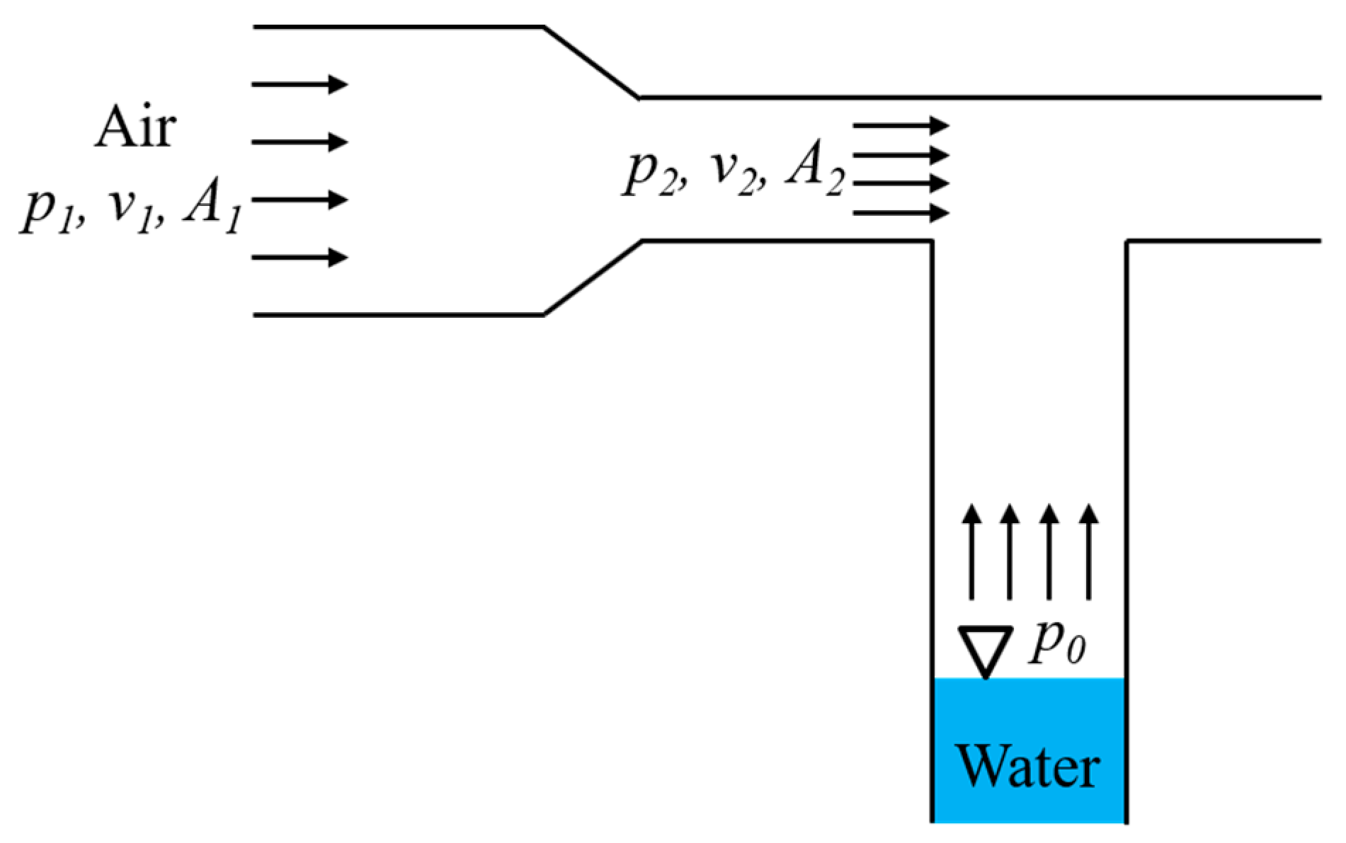
The schematic design of a jet pump is described in Figure 1. The law of quasi-one-dimensional mass conservation leads to:
where v is the axial flow velocity, and A is the cross-sectional area. Equation (1) and the condition result in the unequal equation . For an incompressible, inviscid, and irrotational flow, the Bernoulli’s equation is satisfied in the form:
where p is the static pressure and ρ is the density. Equation (2) and the condition lead to . Subsequently, the pressure is lower than the atmospheric pressure , which is the water inlet pressure. The pressure difference pumps the water upwards.
2.2. Operating Principle of Airlift Pump
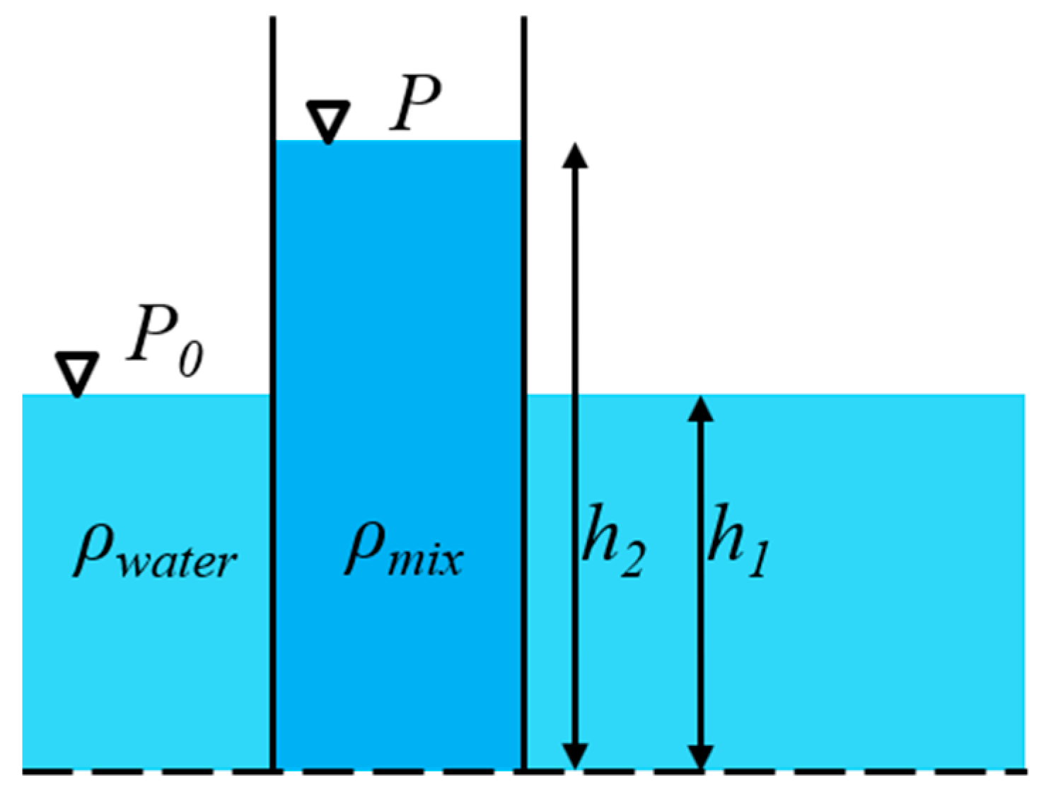
The schematic design of an airlift pump is described in Figure 2. Based on the dotted line in Figure 2, the pressure of water, and that of the water/air mixture are the same, which can be written as:
Because the mixture density is lower than the pure water density, Equation (3) results in . This difference causes water to be pumped up.
2.3. Operating Principle of Hybrid Pump
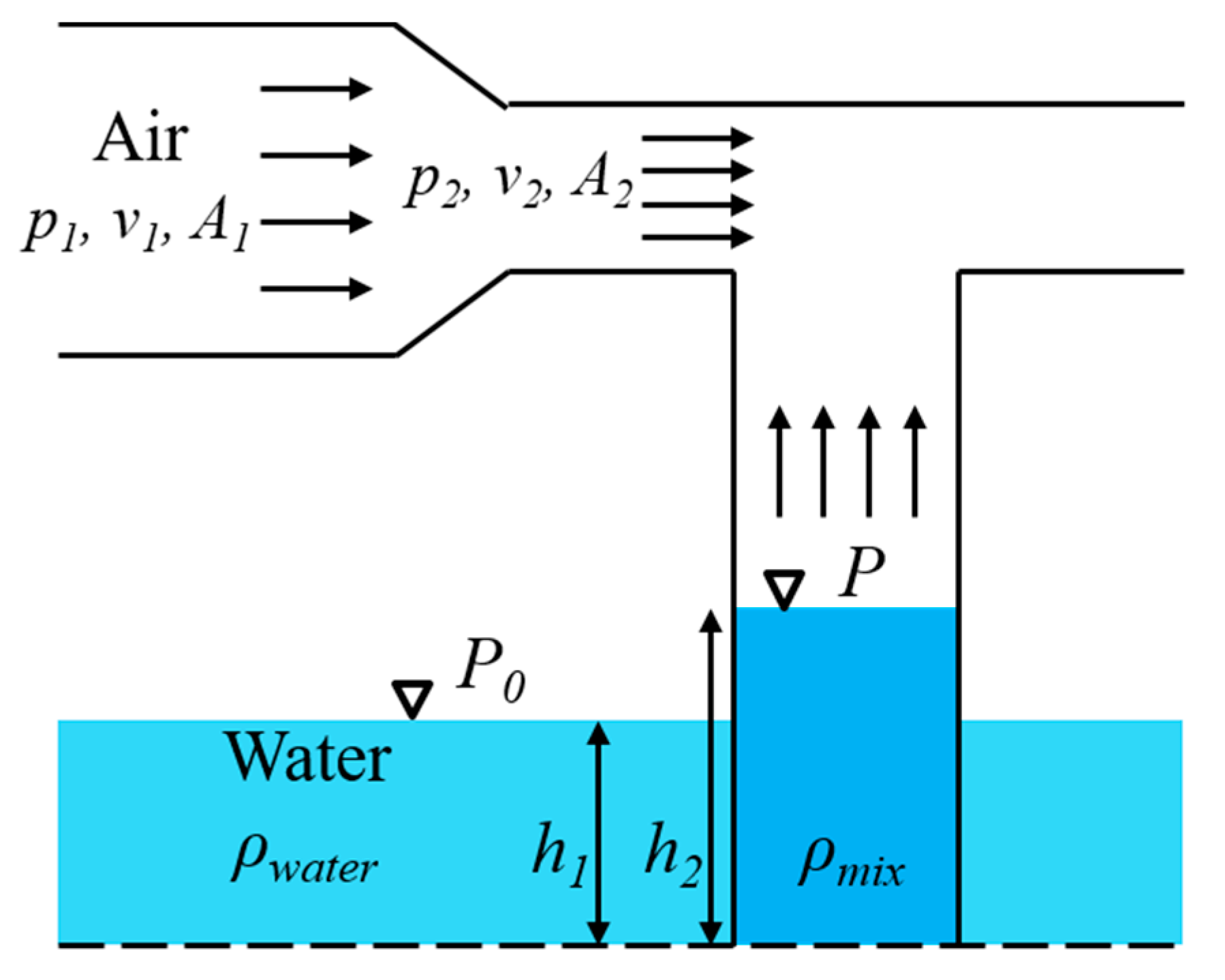
A schematic diagram of the hybrid airlift-jet pump is shown in Figure 3. As described above, the driving force of the jet pump is the pressure difference induced by the nozzle (ejector), while that of the airlift pump is the buoyancy induced by the lower density of the mixture. The basic idea of the hybrid airlift-jet pump, as schematically depicted in Figure 3, is to increase its efficiency by arranging these two driving forces to act complementarily. The upper and lower passages guide the air flow from an air compressor to drive the jet and airlift parts, respectively. The additional advantage of the hybrid pump is its versatile applicability to various operating environments, while retaining its high efficiency by controlling the flow rate entering each passage. For example, when the suction head is high, all the air from the compressor is initially supplied to the airlift part to overcome such a high head height. As the water column approaches the jet part, some of the air is diverted to the jet part to drive the water to the exit of the outlet pipe. After this transient state, the operating condition of the hybrid pump is set to be in the best efficiency or performance condition. A primary goal of the present study is to investigate the performance and efficiency of the hybrid pump in various operating conditions.
3. Governing Equations and Numerical Methods
The compressible unsteady Reynolds-averaged Navier-Stokes equations are used as the governing equations for the flow in the hybrid pump. The homogeneous mixture model, which assumes that each phase traverses at different velocities but with a local equilibrium over short spatial length scales, is used for the two-phase flow. The mixture model consists of the continuity, momentum, and energy equations for the mixture, and the volume fraction equations for the secondary phase. The continuity equation for the mixture can be described as:
where is the mass-averaged mixture velocity vector and is the mixture density. The momentum equation for the mixture can be obtained by adding the individual momentum equations for all phases and be expressed as:
where p is the static pressure, is the viscosity of the mixture, μt is the turbulence viscosity, is the gravity, and is the body force. The energy equation for the mixture assumes the following form:
where keff is the effective conductivity, and T is the temperature. From the continuity equation for the secondary phase p, the volume fraction equation for the secondary phase p can be obtained:
The standard k-ε model is used for the turbulence model and the standard wall function was employed for the near-wall treatment. The effects of turbulence models on two phase numerical solutions were intensively investigated in the preceding study [24]. The standard k-ε turbulent model is based on the transport equations for the turbulent kinetic energy k and its dissipation rate ε, respectively. The transport equations can be written as:
In these equations, Gk represents the generation of turbulence kinetic energy due to the mass-averaged mixture velocity gradients. Gb is the generation of turbulence kinetic energy due to buoyancy. Ym represents the contribution of the fluctuating dilatation in compressible turbulence to the overall dissipation rate. C1ε, C2ε and C3ε are constants. σk and σε are the turbulent Prandtl numbers for k and ε, respectively.
The pressure-based solver in ANSYS Fluent (version 18.2) is used and the pressure–velocity coupling algorithm is chosen as the PISO to obtain a high computational efficiency. The coupling between these variables is achieved via velocity and pressure corrections to enforce both global and local mass conservation. The PRessure STaggering Option (PRESTO!) scheme is used for pressure. First-order upwind schemes are used for density, momentum, energy, volume fraction, turbulence kinetic energy and turbulent dissipation rate. The first-order implicit scheme is used for transient formulation.
For the transient calculation, the time step size was set as 0.001 s to obtain an acceptable CFL number. The converged criteria are set as the residual of 10−3 and the maximum iteration number is set as 20. Monitors of the mass flow rate at the inlets and outlet are set up to assess the performance and efficiency of the pump, and to observe any potential unsteady characteristics.
4. Models of Target Pump
4.1. Geometry Ejector
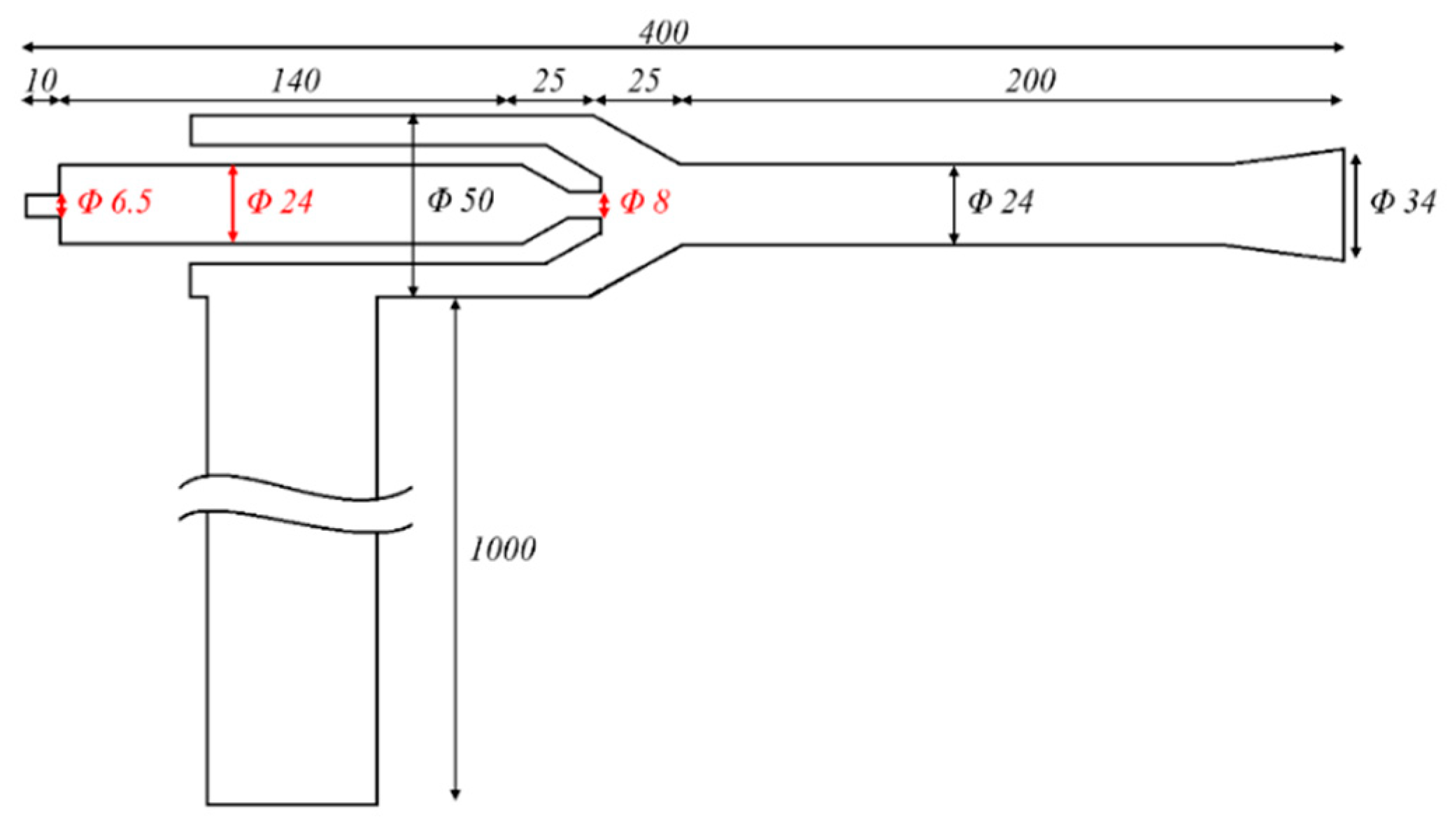
The baseline design of the hybrid airlift-jet pump is shown in Figure 4, which presents the detailed view of the ejector in the jet part. The overall geometric shape and its detailed dimensions of the pump are determined by following the result presented in the previous study. The length of the water suction pipe is set as 1 m. The dimensions and names of the geometric parameters are also listed in Table 1. Note that the air nozzle inlet diameter is set to be the same as the outer diameter of the air compressor used in the experiment.
4.2. Mesh and Boundary Conditions
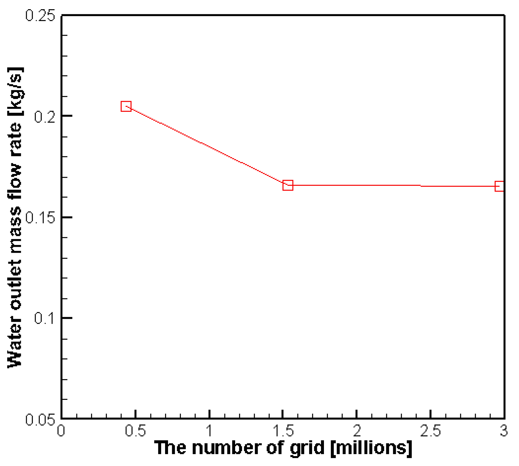
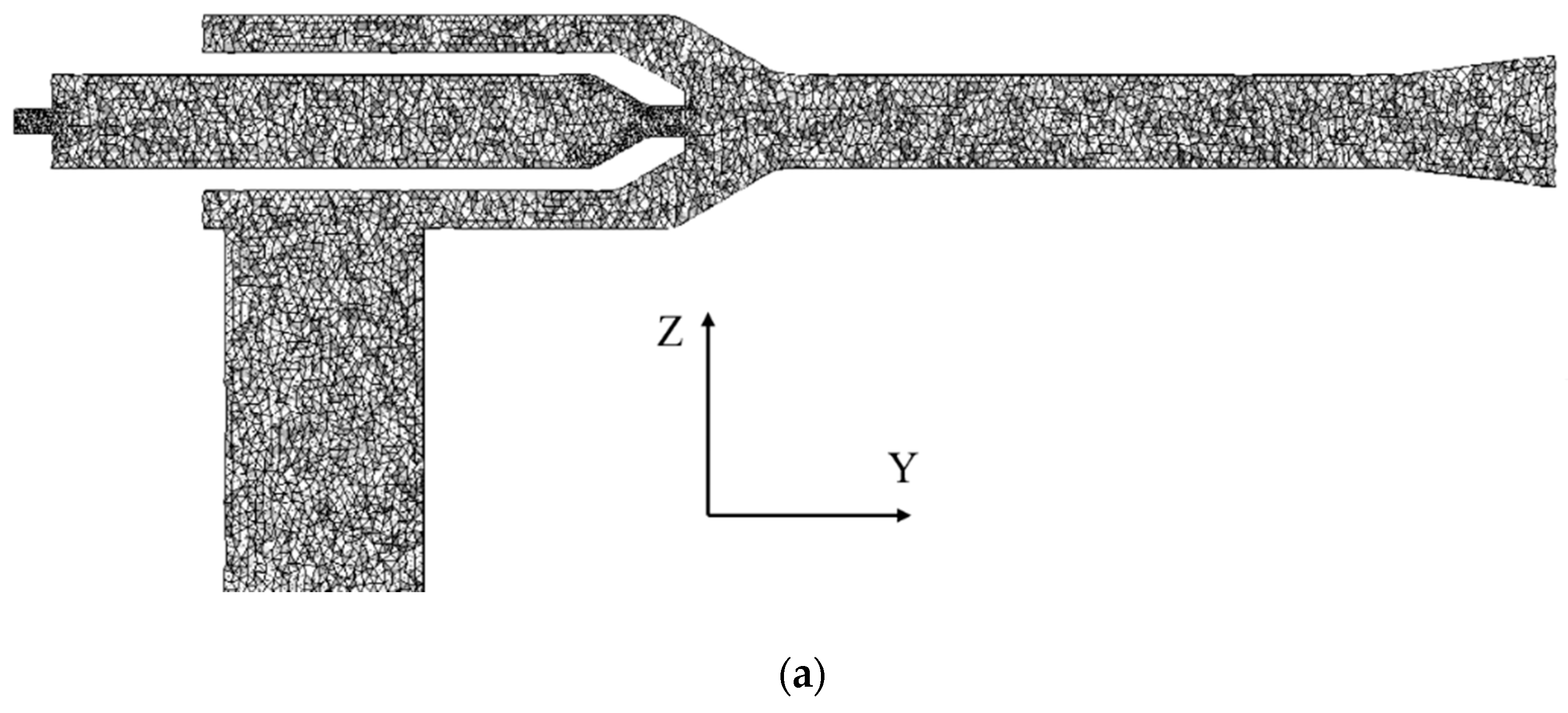
To evaluate the independence of numerical solutions to the mesh used, a grid refinement study is carried out. The boundary conditions of Case No. 7 in Table 2 are applied. Figure 5 shows the result in terms of the water mass flow rate at the outlet and the number of grids used. Based on this result, a mesh of 1.5 million tetrahedron elements, as shown in Figure 6a, is used in the computation domain in all of following computations. The mesh geometries at the air inlet and the air nozzle exit are densified to obtain a more precise simulation of the local detailed flow characteristics, as shown in Figure 6b,c. The mesh size is set to be around 0.25 mm for the air inlet and the air nozzle, and 2.5 mm for the other parts. The maximum y-plus (y+) values are around 500 in the nozzle and 800 in the diffuser.
The total pressure boundary conditions were applied at the inlet section of the air nozzle and the vertical pipe. The range of total pressure at the air inlet is determined according to the capacity of air compressor used in the validation experiment shown in Figure 7. The total pressure at the water inlet is determined by including the effects of suction pipe length submerged in water; the total pressures of 1 kPa and 6 kPa correspond to the submerged suction pipe height (shown in Figure 7g) of 0.1 m and 0.6 m, respectively. However, the volume fraction of water at the water inlet, which depends on the capacity of air compressor, the generated cavitation types and the water flow velocity (water mass flow rate) are relatively difficult to determine. Therefore, the range of water volume fraction at the water inlet is set to investigate the effects of airlift pump on the overall performance of hybrid pump in its wide operation range. Altogether, eighteen cases are investigated including the operating conditions of only the jet part, and both the airlift and jet parts. For the jet-pump-only operation, the total pressure at the air inlet is varied along with specifying the volume fraction of air as one. At the water inlet, the volume fraction of air is specified as zero. In the hybrid mode, for simplicity, the volume fraction of air, as well as the total pressure at the water inlet, is varied to simulate the effects of the airlift pump and the submerged suction pipe height. The total pressure equation can be written as:
where pT is the total pressure, pS is the static pressure, M is the Mach number and γ is the ratio of specific heats.
The boundary conditions of each case are listed in Table 2. The total pressure boundary conditions are set at the air and water inlets. At the outlet, the static pressure condition is applied and set as zero gauge pressure. The total pressure range at the air inlet is varied from 100 kPa to 400 kPa. The cases denoted by No. 1–8 are set to simulate the influence of the air inlet pressure for different water inlet pressures, which are determined to represent different suction lengths (interpreted as the water suction pipe being buried into water or reducing the length of the suction pipe). Cases No. 9–12 are set to investigate the performance of the hybrid airlift-jet pump in different air inlet pressures; Cases No. 14–18 are set to different volume fractions of water at the water inlet. Case No. 13 is one example where both the abovementioned conditions are applied simultaneously. The hybrid initialization method that solves the Laplace equation is used.
5. Results and Discussion
5.1. Validation of Numerical Methods
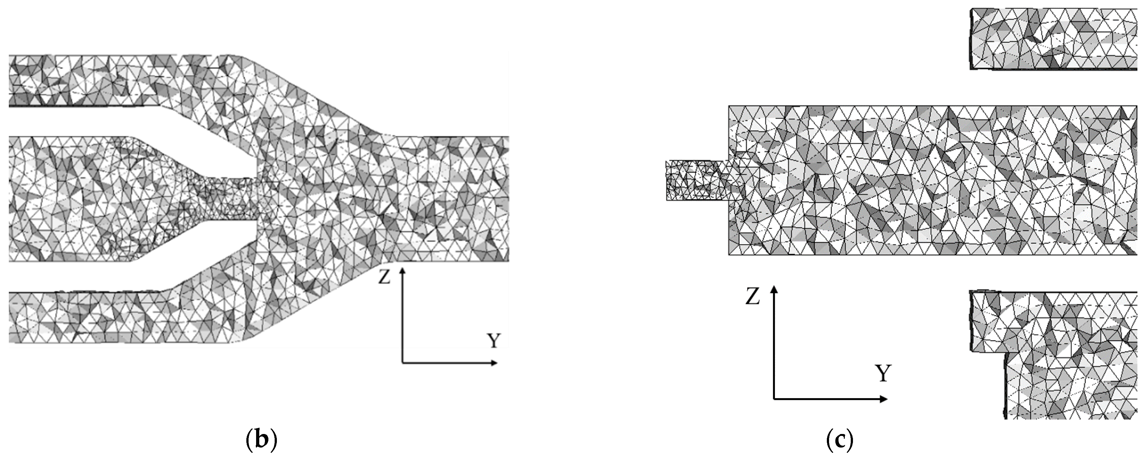
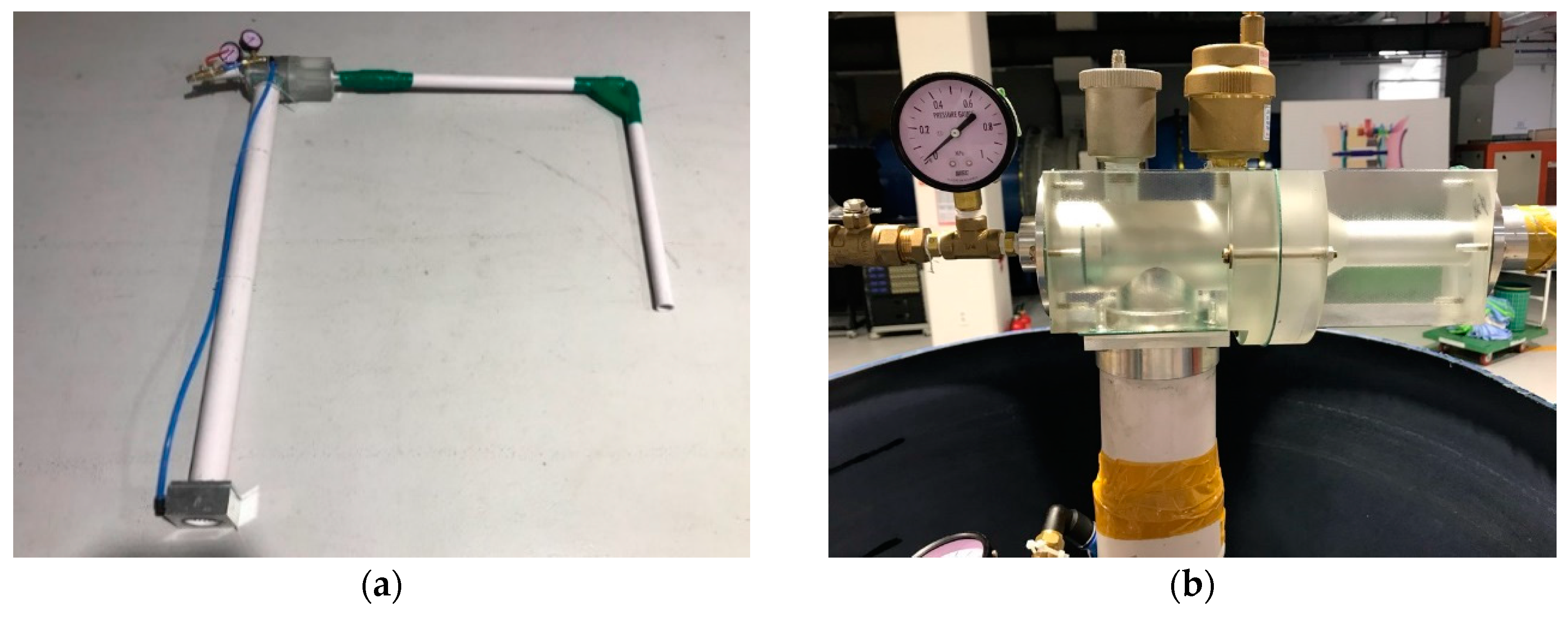
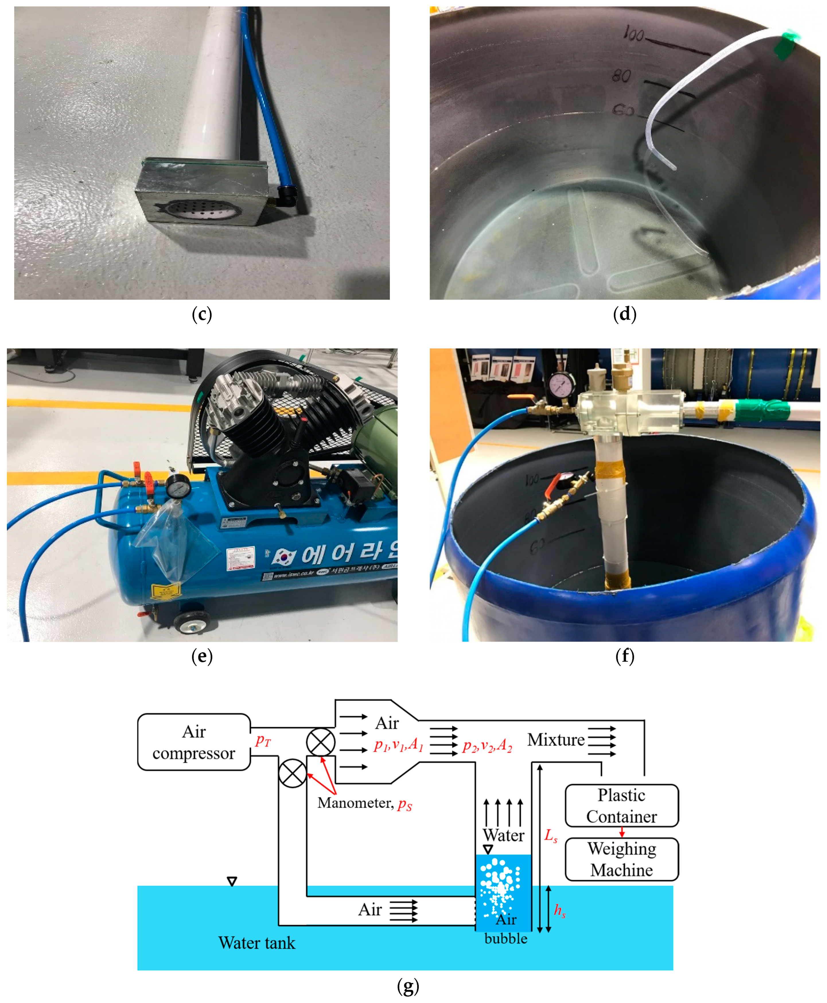
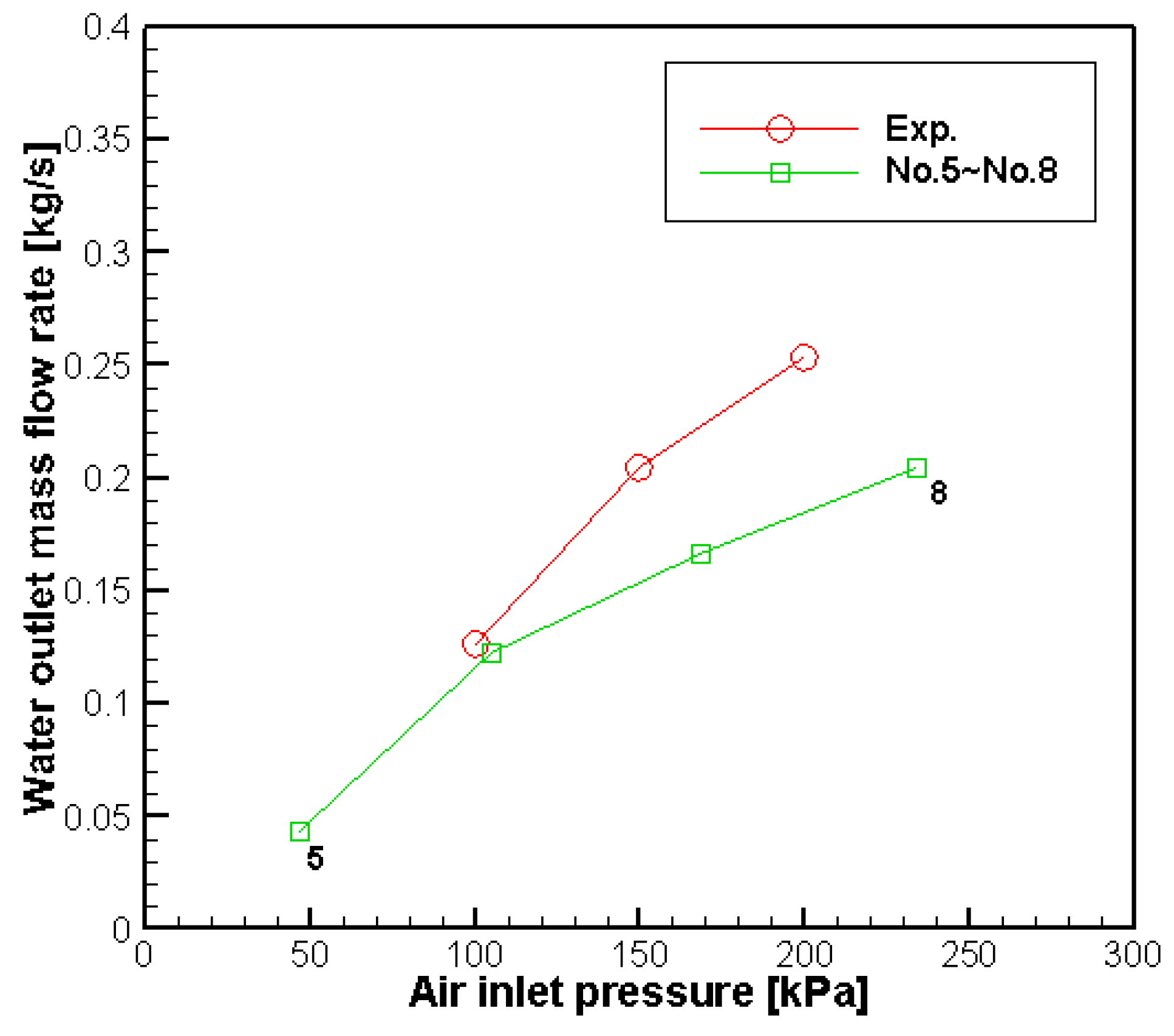
To validate the current numerical methods, experiments using the prototype hybrid pump shown in Figure 7 are performed. The air compressor of SP5-150-5 [25] is used and can compresses air up to 9.0 bar. The prototype hybrid pump is connected to the air compressor to provide the air source to the jet and airlift parts. Among the cases listed in Table 2, Cases of No. 5–8 that represent the sole operation of the jet part for the submerged height of 0.6 m are selected for comparison. Figure 7 shows the water tank, the air compressor and the prototype hybrid pump connected to the air compressor, together with the schematics of the experimental setup. The static pressure at the inlet of the jet pump is measured by using the manometer of P110 [26], which can be measured up to 1 MPa, and the water mass flow rate is measured by weighing the water expelled from the pump during 10 s.
Figure 8 compares the variation in static pressure at the inlet of the airflow versus the water flow rate between the experimental and computation results. Although the difference between the two results increases as the static pressure increases, a good agreement between the two results is found in terms of the increasing trend of water mass flow rate at the outlet, as the air inlet pressure increases. The larger difference at the higher air inlet pressure seems to be due to the fact that the numerical simulation assumes the constant total pressure at the water inlet, while the total pressure in the experiment decreases with a reduction in the submerged suction pipe height when water in the tank is pumped out. The more realistic boundary condition may be needed to reproduce the experimental condition more closely. However, since the aim of present study is to assess the relative performance and efficiency of the hybrid pump in various operation conditions, the validation of the present numerical method is sufficient in this respect.
5.2. Performance and Efficiency of Hybrid Pump
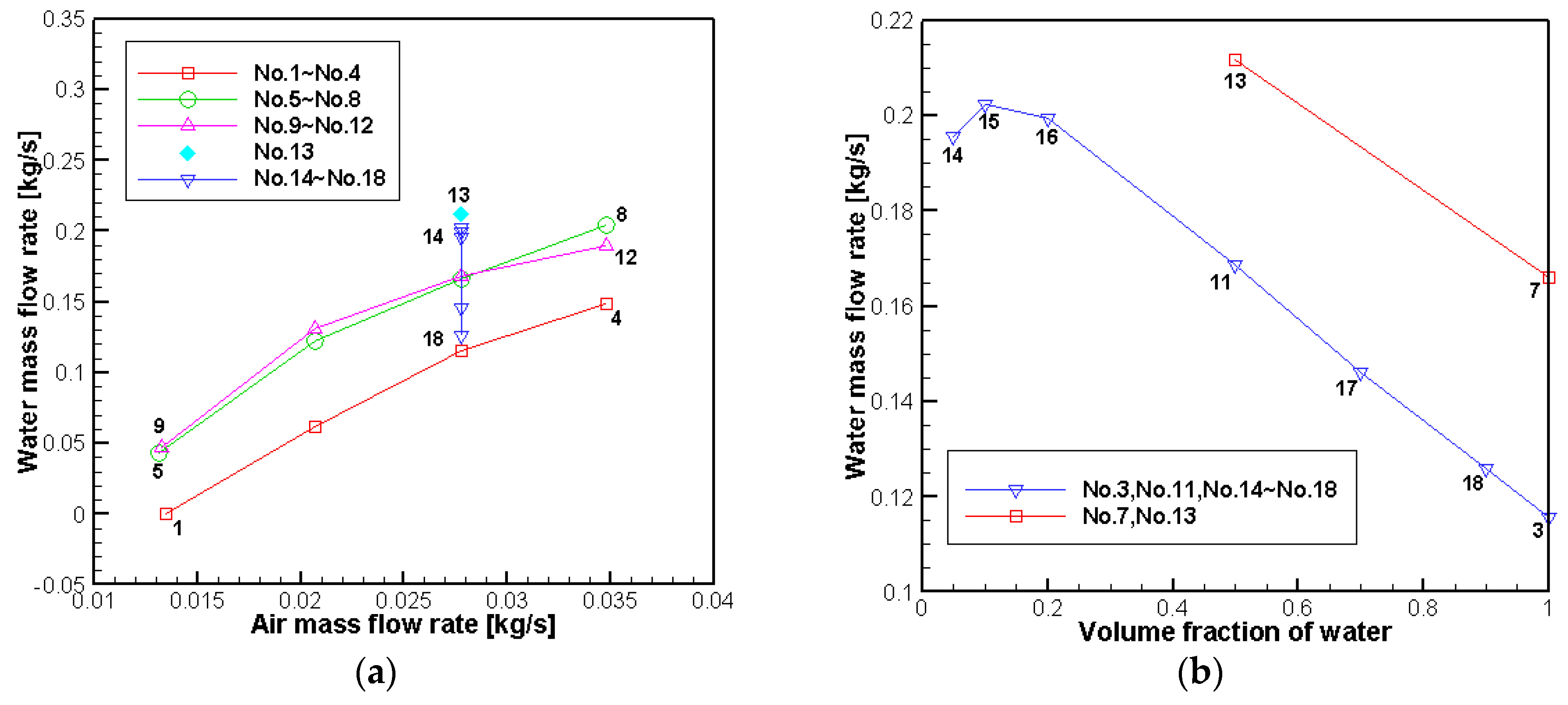
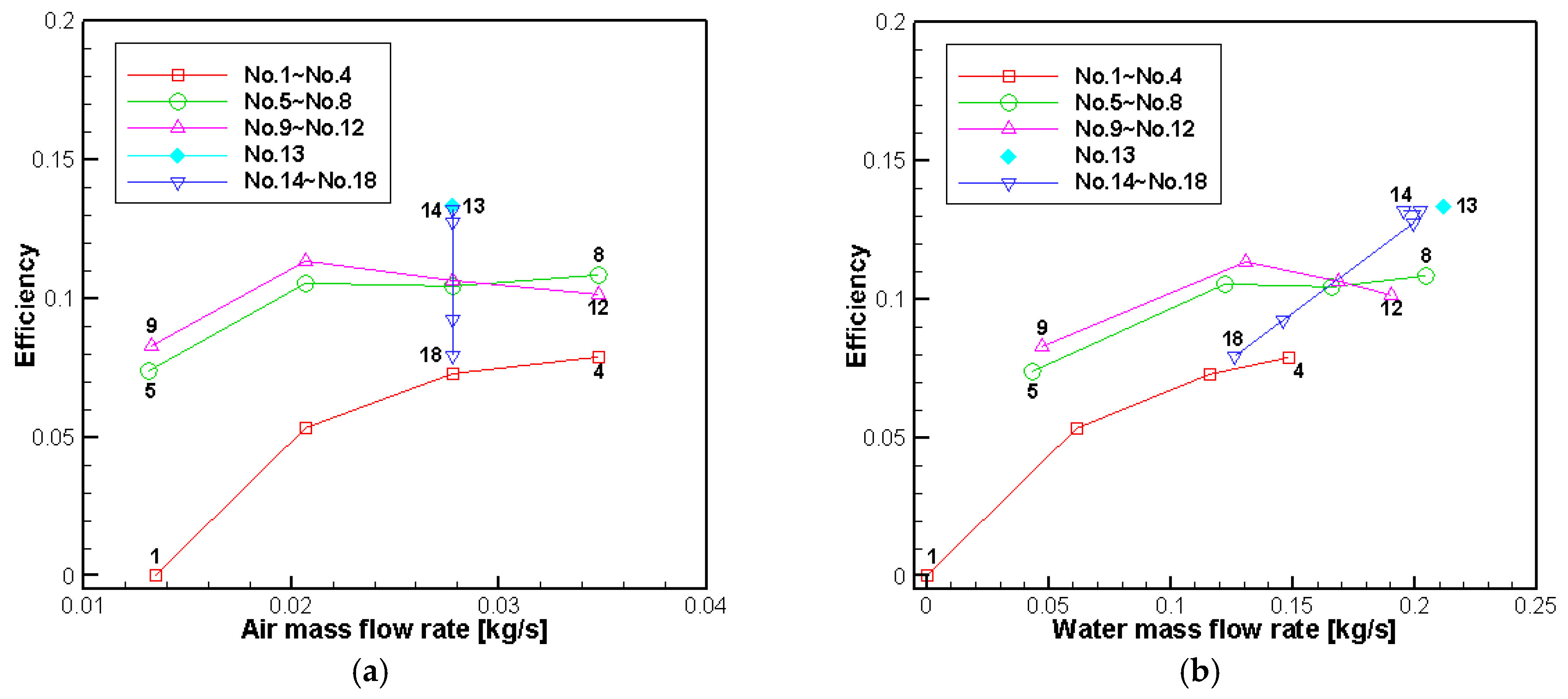
Figure 9a,b shows the average mass flow rate of the water versus the average mass flow rate of the air for all of the cases and the average mass flow rate of the water versus the water volume fraction at the water inlet for the hybrid cases, respectively. As shown in Case No. 1, the mass flow rate of water is zero, implying that the airflow is not sufficiently strong to pump the water to 0.9 m high. For the other cases, the water mass flow rate increases with the air mass flow rate. In Cases No. 5–8, which are set to simulate a shorter suction height of 0.4 m, the air mass flow rate does not change enormously in the same air inlet boundary condition, while the water mass flow rate is increased significantly in comparison with Cases No. 1–4. This relatively larger mass flow rate is due to the less work required to obtain gravitational potential energy with almost the same energy from the air flow. In the hybrid pump, Cases No. 9–18 where the jet and airlift parts operate together are also shown in Figure 9a. When the volume fraction of water is set to be 0.5 at the water inlet (Cases No. 9–12), it shows a similar mass flow rate in Cases No. 5–8, which represent a shorter pipe suction length. The similarity here is considered to be related to less work required in the suction pipe owing to the lower mixture density or shorter suction height. When the hybrid pump case is performed with a shorter suction pipe length (Case No. 13), a more significant increase in the water mass flow rate is achieved. For the hybrid pump cases with different volume fractions of water (Cases No. 14–18), their water mass flow rates increase as the water volume fraction decrease to the value of 0.1; when the water volume fraction is further reduced to below 0.1, the water mass flow rate decreases, that is, the water mass flow rate in Case No. 14 is less than that in Case No. 15. The maximum water mass flow rate is achieved through Case No. 13, with a value of 0.21 kg/s. The effects of the water inlet volume fraction and the water suction height on the water mass flow rate can be seen in Figure 9b.
To compare the performance of the pump operating under different conditions more quantitatively, the efficiency of the hybrid airlift-jet pump is defined as:
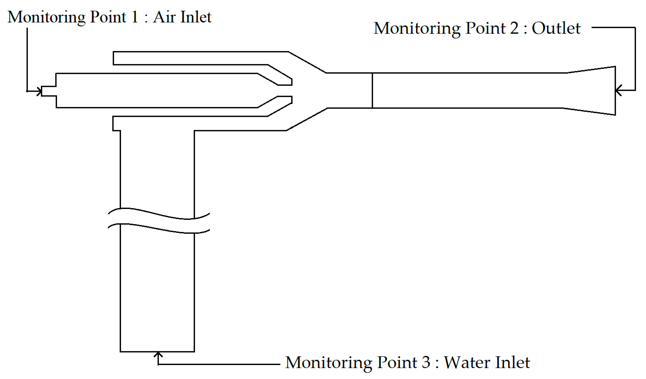
where represents the mass flow rate of the fluid; the subscripts w and a represent the water and air, respectively; the subscripts 1, 2, 3 denote the monitoring locations, as shown in Figure 10; H is the total head of water or air in a certain location, which can be expressed as:
Equation (11) is typically used for assessing the performance of the jet pump; however, it is also suitable for the hybrid pump. With only normal-pressure air being released at the water inlet, the additional input power is sufficiently small to be ignored owing to its low kinetic energy and small mass flow rate at the water inlet. Therefore, the equation is still valid provided that the state for each phase is correctly monitored at every boundary. However, note that Equation (11) needs to be corrected if the airlift part is modeled in more realistic ways: for example, the water volume fraction boundary condition is replaced with air-injection with higher pressure.
The predicted efficiency, the air mass flow rate, and the water mass flow rate in each case are shown in Figure 11. Figure 11a shows a similar relationship to that in Figure 9a. A higher efficiency is generally achieved when more air is injected as the air inflow in Cases No. 1–8, while the efficiency decreases in higher airflow rates for Cases No. 10–12. The efficiency for each air inlet boundary condition improves in the cases of a shorter suction length (Cases No. 5–8), a hybrid pump setting (Cases No. 9–12), or both (Case No. 13) in comparison with Cases No. 1–4. The maximum efficiency (13.3%) is achieved through Case No. 13, as indicated in Figure 11b, because, more water is suctioned for a favorable case setting at the same efficiency.
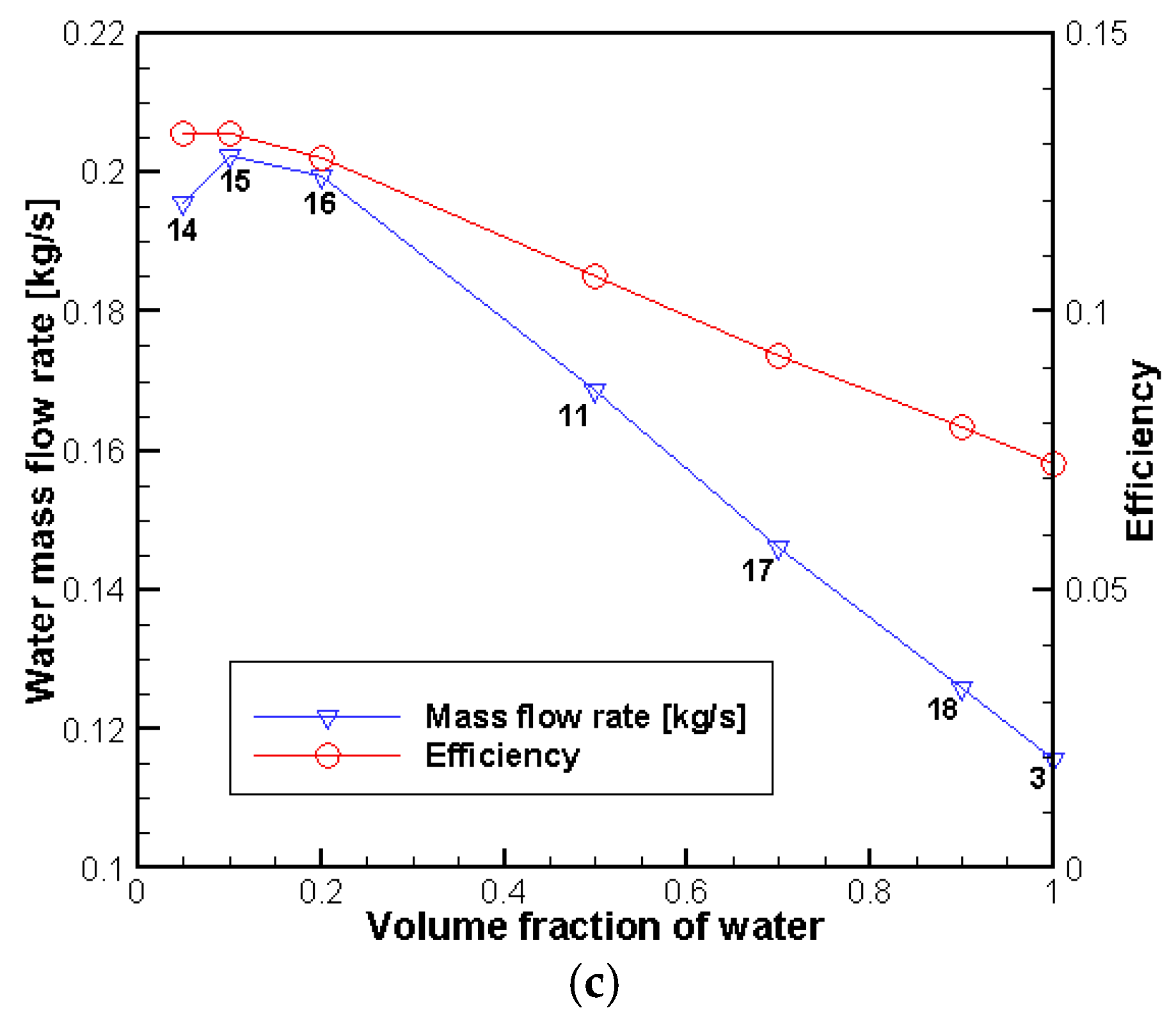
The variations in the water mass flow rate and efficiency in terms of varied volume fractions in Cases No. 3, No. 11, and No. 14–18 are shown in Figure 11c. Both variables initially increase when the hybrid pump setting is activated by injecting air into the water column, while a relative low volume fraction of water restricts the increase in mass flow rate when a great deal of air is injected. The maximum point for the mass flow rate is achieved at the volume fraction of 0.1. However, the efficiency curve continues to increase without a maximum point. The velocity of the outlet water increases continually even when the volume fraction is small, resulting in a high efficiency.
5.3. Pressure and Velocity Distributions inside Hybrid Pump
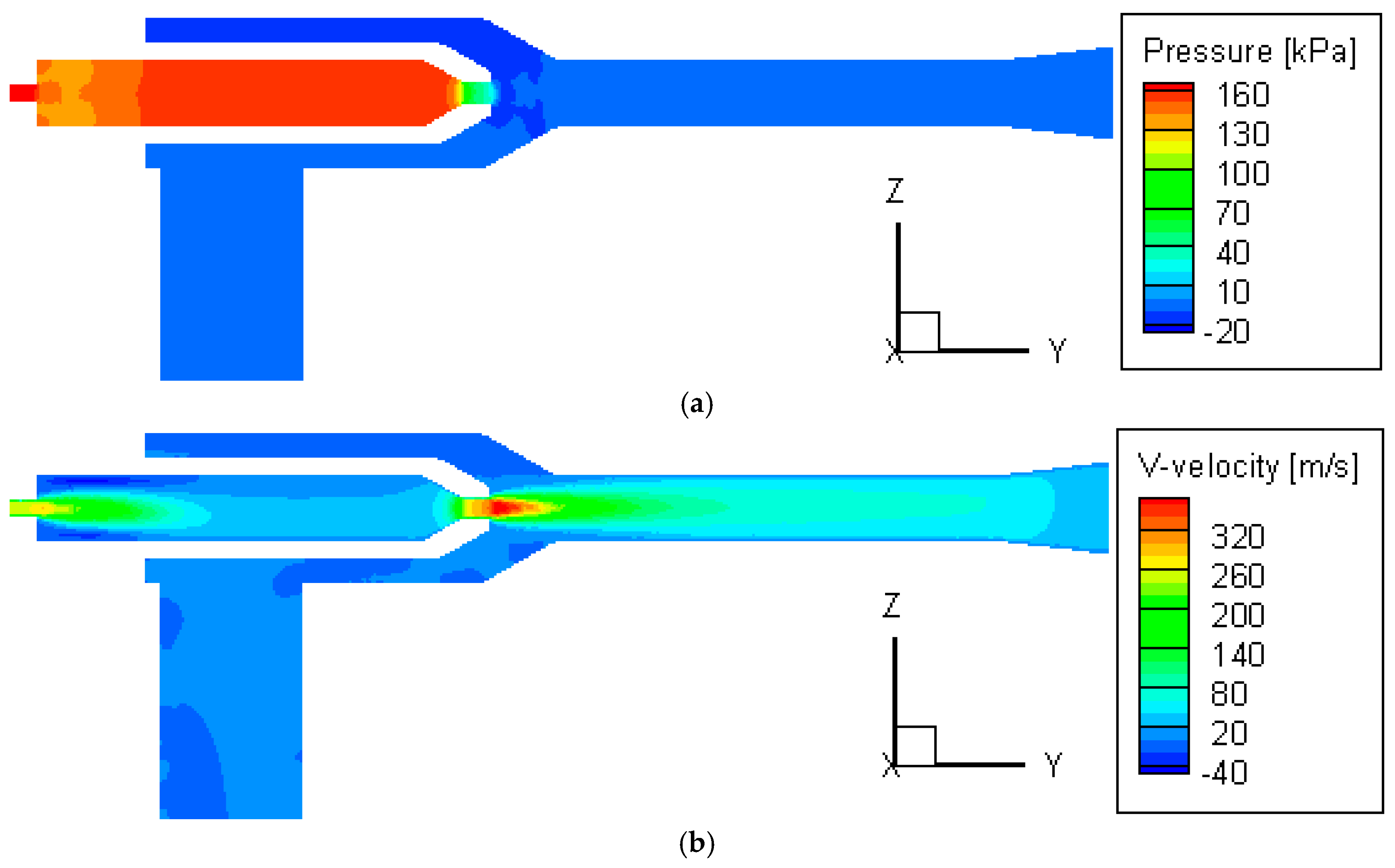
Case No. 3 is chosen to illustrate the characteristics of the two-phase flow field inside the hybrid pump by investigating the detailed distributions of static gauge pressure and fluid velocity. As shown in Figure 12a, the air pressure decreases rapidly when it arrives at the air nozzle part. Just outside of the air nozzle (ejector), a negative pressure area forms. In Figure 12b, the maximal axial velocity is observed in the exit of the air nozzle, although the flow path is enlarged. This is due to the decrease in pressure that causes the air to obtain a significant expansion.
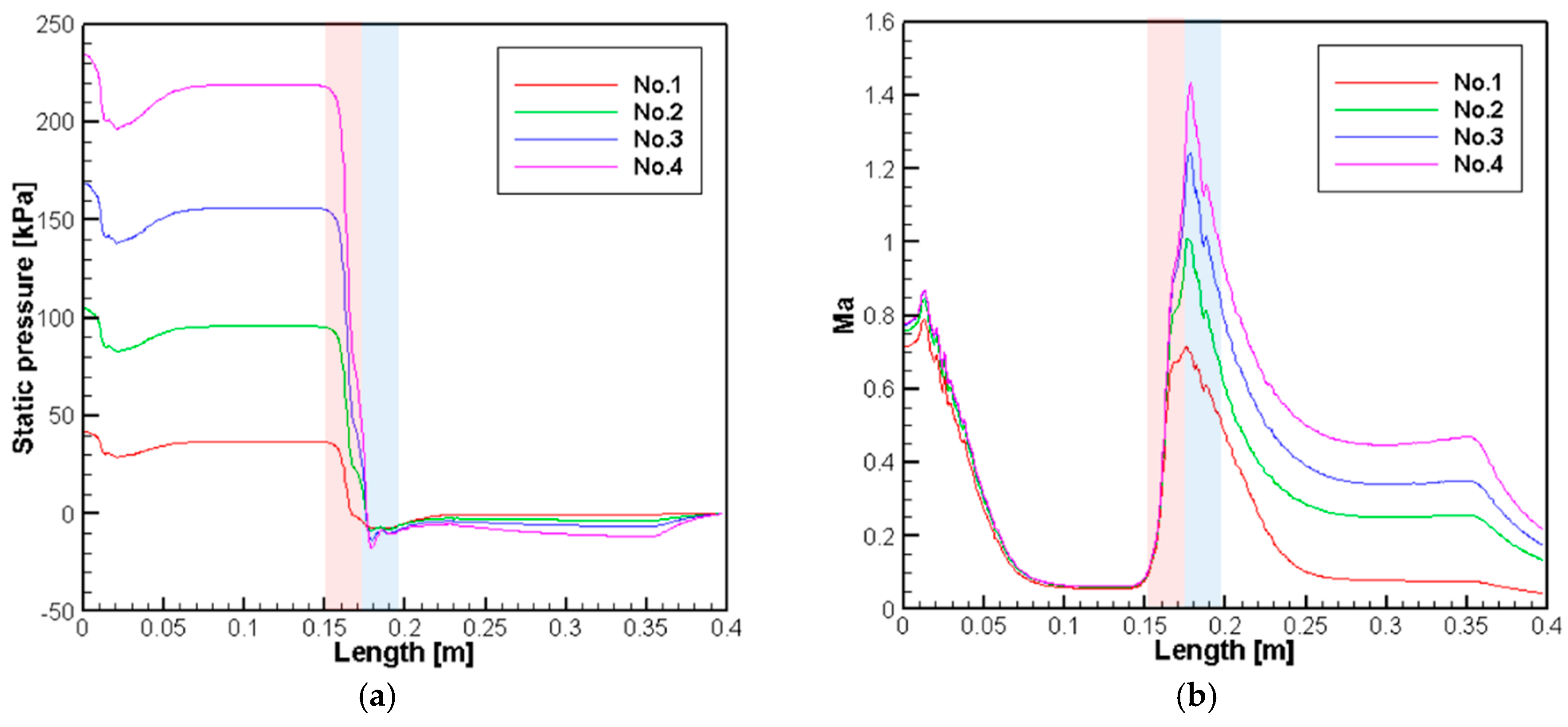
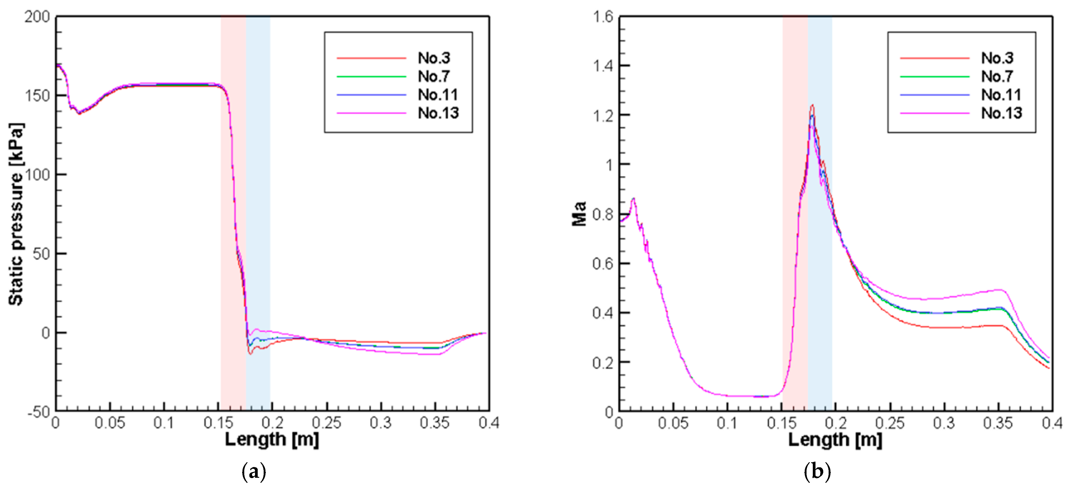
The static gauge pressures and the Mach numbers of the air along the center line of the air nozzle and the primary exit pipe are shown in Figure 13, where Cases No. 1–4 are chosen to illustrate the relationship between these variables and the air inlet total pressure. It is noteworthy that the remaining cases share the similar trend. In each case, the negative gauge pressure is formed at the air nozzle exit due to the expansion of air. When the static pressure difference between the inlet and the outlet of pipe flow increases, the air flow is accelerated along the converging nozzle, and a choked flow is formed, in which the Mach number is maintained to be one in the nozzle. However, if the pressure difference continues to increase, the Mach number at the nozzle is maintained at 1, but the downstream flow is more accelerated to be supersonic in the diffusion region [27]. Note that the increase of the static pressure and the decrease of Mach number near the exit of main pipe are due to the diverging diffuser, as shown in Figure 12.
Table 3 shows the inlet static pressures and the maximum Mach numbers along the center line of the air nozzle and the primary exit pipe. The static pressure at the air inlet increases and the minimum value decreases as a higher total pressure boundary condition is set at the air inlet. Meanwhile, a negative gauge pressure in the mixing section appears to be more obvious with a higher inlet total pressure, causing the pressure in the diffuser to recover more quickly. As shown in Figure 13b, despite the different inlet pressure distributions, the velocity in the air nozzle is almost the same at the inlet as that at the middle section of the air nozzle. At the air nozzle exit, air with a higher inlet pressure boundary condition increases significantly in velocity; the velocity difference persists until the air reaches the outlet of the diffuser.
To compare the cases with different suction heights and volume fractions that are affected by the operation of the airlift part, distributions of static pressure and the Mach number in the cases with the same air inlet total pressure of 300 kPa are shown in Figure 14. In the static pressure distribution, compared with Case No. 3, the other cases have a smaller negative pressure at the air nozzle exit but a larger negative pressure in the primary exit pipe of the mixing section. A more obvious difference can be found in the Mach number plot, as the case with a shorter suction height and a lower volume fraction of water has a higher Mach number at the mixing section. Case No. 13 shows the highest Mach number distribution owing to the superposition of the two effects.
5.4. Periodic Fluctuation of Water Flow
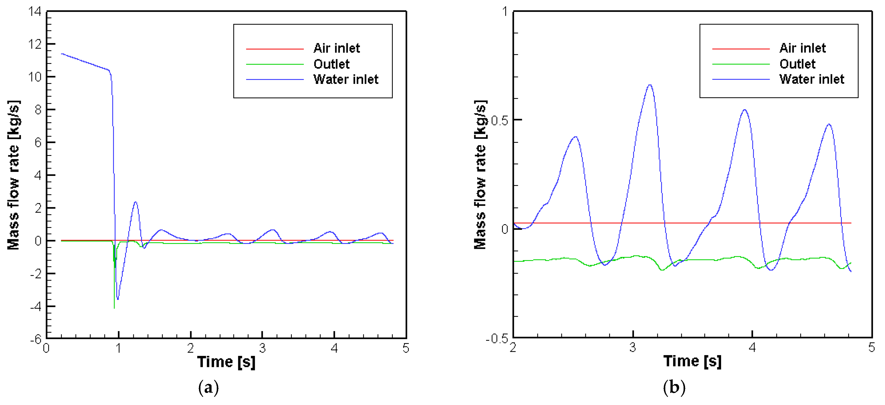
The time history of the mass flow rate of Case No. 3 is shown in Figure 15. Note that the positive sign at the boundary means the flow into the system, while the negative sign at the outlet means the positive mass flow rate. Initially, a relatively high mass flow rate appears at the water inlet, which represents the water being pumped up from the downside as the jet pump starts to operate. When the water phase reaches the mixing section, an initial instability occurs, which leads to a strong back flow to the water inlet. Simultaneously, a large amount of water is exhausted in comparison to the water mass flow rate at the outlet. After this initial unstable fluctuation, the water mass flow rates at the outlet and water inlet are developed into a periodic fluctuation with a period of approximately 0.8 s. The back flow to the water inlet occurs at every fluctuation period.
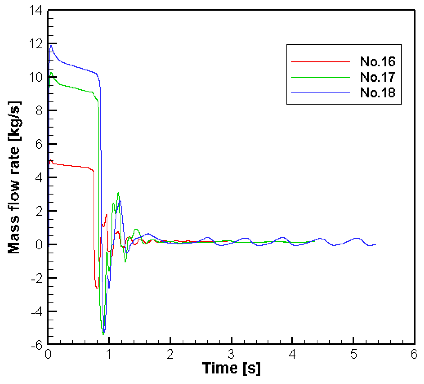
To confirm this periodic fluctuation of water mass flow rate at the inlet, the time histories of the inlet water mass flow rate computed for the other cases are shown in Figure 16. The time span is not exactly the same in every case, because the unsteady computation is halted after the converged solution is obtained to save computational time. Cases No. 16–18 represent water volume fraction boundary conditions of 0.2, 0.7, and 0.9, respectively. As shown in the comparison in Figure 16, the fluctuation pattern of the inlet water mass flow rate is similar to that in the jet-pump-only case (Case No. 3), where the volume fraction of water is set as 0.9. An attenuated pattern of mass flow rate fluctuation is formed when the volume fraction of water further decreases.
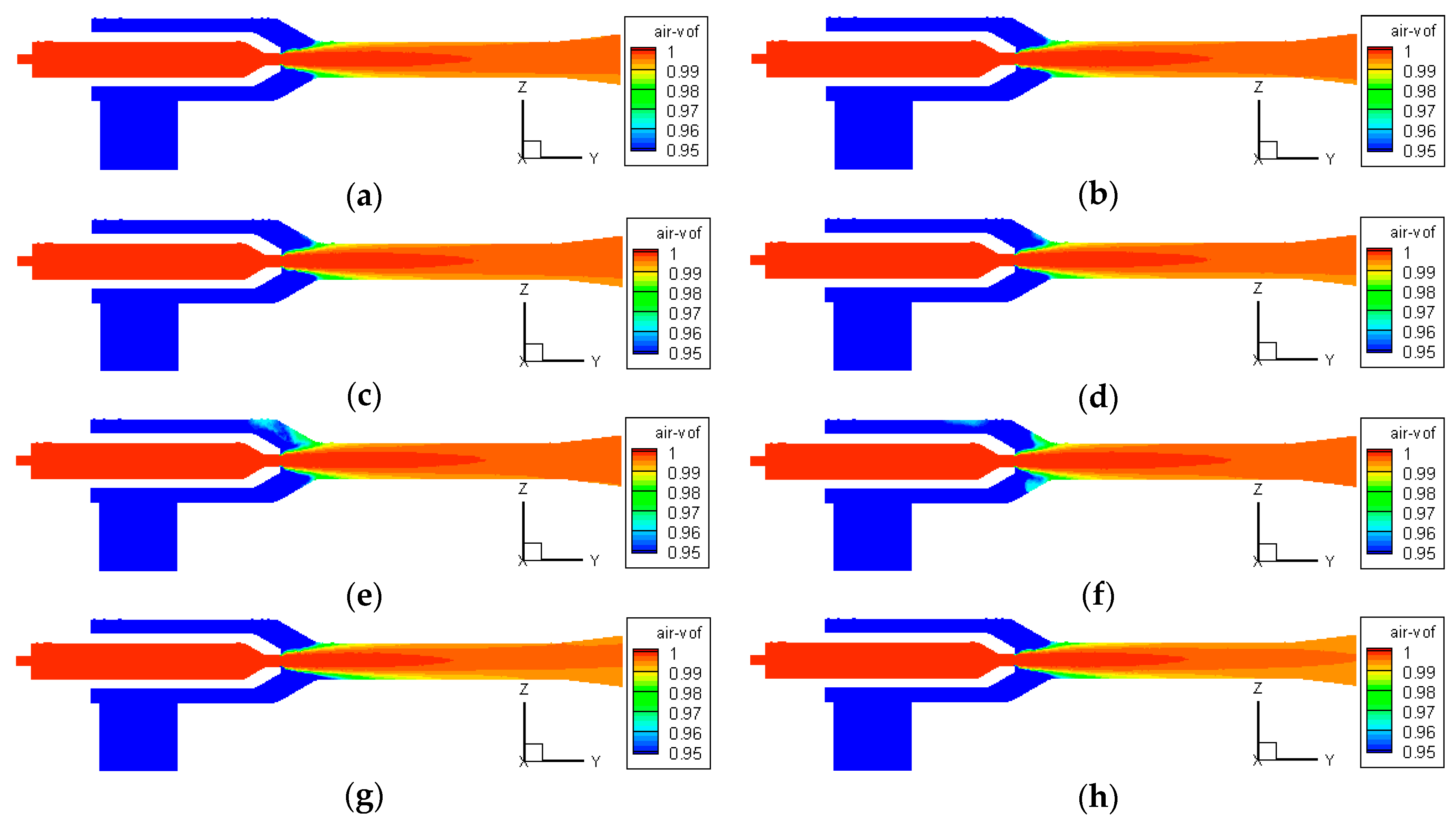
The detailed distributions of volume fraction at different time steps in Case No. 3 are shown in Figure 17. Altogether, eight time steps are chosen according to the periodic fluctuation of the water mass flow rate observed in Figure 17. More water is entering the mixing section and the diffuser, respectively, as shown in Figure 17e,f; this corresponds to the time step with a local maximum value of the mass flow rate. As a contrast, the volume fraction of water at the same section is much lower in Figure 17g,h. With the fluctuation of the water mass flow rate, a pulsating pump phenomenon occurred. This may be explained by the air being periodically blocked by the inlet water, which caused the instability in the pump’s suction ability. Further, this may explain why this phenomenon is not remarkable in the hybrid pump cases when air is released into the water inlet and weakened the blocking effect. This is an advantage in activating the hybrid pump phase.
6. Conclusions
Numerical simulations of 18 cases were performed to investigate the performance of the preliminary design of a hybrid airlift-jet pump under various operational conditions. The water mass flow rate increases with the higher total pressure boundary conditions at the air inlet. With the same air inlet conditions, an improvement in pumping ability can be achieved by shortening the suction height, releasing air into the water inlet to form a hybrid pump case, and applying a combined case of the abovementioned settings. Using the efficiency definition applicable for the current study, it is shown that the efficiency for each air inlet boundary condition improves when a shorter suction length is applied or a volume fraction of water is decreased in the hybrid pump phase. The best volume fraction rate of water to obtain a large mass flow rate is 0.1 for the current design.
The static pressure distribution shows an area of negative pressure from the outlet of the air nozzle to the diffuser in each case. The velocity distribution indicates that despite the different pressure values in the air nozzle, the air travels at almost the same speed for the different cases. The difference in velocity only occurs near the outlet of the air nozzle.
The fluctuating mass flow rates of water in different cases, as well as the volume fraction counters, are analyzed, which shows a periodic fluctuating phenomenon of the water flow. The inlet water mass flow rate fluctuates, thus forming a pulsating pump system. This phenomenon is attributable to the air being periodically blocked by the water and weakened in the hybrid pump cases.
These results confirm that the performance of the jet or airlift pump can be enhanced by employing the hybrid airlift-jet pump newly proposed in the present study. In the future, this preliminary conceptual design will be improved by optimizing design factors, such as the nozzle, the mixing chamber and the suction pipe, on a basis of more intensive and extensive numerical and experimental analysis on flow characteristics of the hybrid pump. The numerical methods also need to be improved by modelling the airlift part in a more realistic way: an air-injection boundary condition will be considered instead of the water volume fraction boundary condition.
Author Contributions
I.L. proposed the initial concept of new hybrid pump. C.C. refined the initial concept of hybrid pump and supervised the entire research. D.Y. performed the related numerical computations and prepared the first draft of paper. K.L. carried out the related experiments. M.H. reran all of the numerical simulations in the preparation of revised manuscript.
Funding
This research received no external funding.
Acknowledgments
This research was supported by Basic Science Research Program through the National Research Foundation of Korea (NRF) funded by the Ministry of Education (No. 2016R1D1A1A09918456).
Conflicts of Interest
The authors declare no conflicts of interest.
References
- Rankine, W.J.M. On the mathematical theory of combined streams. Proc. R. Soc. Lond. 1870, 19, 90–94. [Google Scholar]
- Keenan, J.H. An investigation of ejector design by analysis and experiment. J. Appl. Mech. 1950, 17, 299–318. [Google Scholar]
- Eames, I.W.; Aphornratana, S.; Haider, H. A theoretical and experimental study of a small-scale steam jet refrigerator. Int. J. Refrig. 1995, 18, 378–386. [Google Scholar]
- Huang, B.J.; Chang, J.M.; Wang, C.P.; Petrenko, V.A. A 1-D analysis of ejector performance. Int. J. Refrig. 1999, 22, 354–364. [Google Scholar]
- Riffat, S.B.; Gan, G.; Smith, S. Computational fluid dynamics applied to ejector heat pumps. Appl. Therm. Eng. 1996, 16, 291–297. [Google Scholar] [CrossRef]
- Riffat, S.B.; Omer, S.A. CFD modelling and experimental investigation of an ejector refrigeration system using methanol as the operating fluid. Int. J. Energy Res. 2001, 25, 115–128. [Google Scholar] [CrossRef]
- Zhu, Y.; Cai, W.; Wen, C.; Li, Y. Numerical investigation of geometry parameters for design of high performance ejectors. Appl. Therm. Eng. 2009, 29, 898–905. [Google Scholar]
- Li, C.; Li, Y.Z. Investigation of entrainment behavior and characteristics of gas–liquid ejectors based on CFD simulation. Chem. Eng. Sci. 2011, 66, 405–416. [Google Scholar]
- Fan, J.; Eves, J.; Thompson, H.M.; Toropov, V.V.; Kapur, N.; Copley, D.; Mincher, A. Computational fluid dynamic analysis and design optimization of jet pumps. Comput. Fluids 2011, 46, 212–217. [Google Scholar] [CrossRef]
- Shah, A.; Chughtai, I.R.; Inayat, M.H. Experimental and numerical analysis of steam jet pump. Int. J. Heat Fluid Flow 2011, 37, 1305–1314. [Google Scholar] [CrossRef]
- Shah, A.; Khan, A.H.; Chughtai, I.R.; Inayat, M.H. Numerical and experimental study of steam-water two-phase flow through steam jet pump. Asia Pac. J. Chem. Eng. 2013, 8, 895–905. [Google Scholar] [CrossRef]
- Narabayashi, T.; Wataru, M.; Michitugu, M. Study on two-phase flow dynamics in steam injectors. Nucl. Eng. Des. 1997, 175, 147–156. [Google Scholar] [CrossRef]
- Narabayashi, T.; Mori, M.; Nakamaru, M.; Ohmori, S. Study on two-phase flow dynamics in steam injectors: II. High-pressure tests using scale-models. Nucl. Eng. Des. 2000, 200, 261–271. [Google Scholar] [CrossRef]
- Bartosiewicz, Y.; Aidoun, Z.; Desevaux, P.; Mercadier, Y. Numerical and experimental investigations on supersonic ejectors. Int. J. Heat Fluid Flow 2005, 26, 56–70. [Google Scholar] [CrossRef]
- Yan, J.J.; Shao, S.F.; Liu, J.P.; Zhang, Z. Experiment and analysis on performance of steam-driven jet injector for district-heating system. Appl. Therm. Eng. 2005, 25, 1153–1167. [Google Scholar] [CrossRef]
- Chong, D.T.; Yan, J.; Wu, G.; Liu, J. Structural optimization and experimental investigation of supersonic ejectors for boosting low pressure natural gas. Appl. Therm. Eng. 2009, 29, 2799–2807. [Google Scholar] [CrossRef]
- Kassab, S.Z.; Kandil, H.A.; Warda, H.A.; Ahmed, W.H. Air-lift pumps characteristics under two-phase flow conditions. Int. J. Heat Fluid Flow 2009, 30, 88–98. [Google Scholar] [CrossRef]
- Taitel, Y.; Bornea, D.; Dukler, A.E. Modelling flow pattern transitions for steady upward gas-liquid flow in vertical tubes. AIChE J. 1980, 26, 345–354. [Google Scholar] [CrossRef]
- De Cachard, F.; Delhaye, J.M. A slug-churn flow model for small-diameter airlift pumps. Int. J. Multiph. Flow 1996, 22, 627–649. [Google Scholar] [CrossRef]
- Furukawa, T.; Fukano, T. Effects of liquid viscosity on flow patterns in vertical upward gas–liquid two-phase flow. Int. J. Multiph. Flow 2001, 27, 1109–1126. [Google Scholar] [CrossRef]
- Fujimoto, H.; Ogawa, S.; Takuda, H.; Hatta, N. Operation performance of a small air-lift pump for conveying solid particles. J. Energy Resour. Technol. 2003, 125, 17–25. [Google Scholar] [CrossRef]
- Khalil, M.F.; Elshorbagy, K.A.; Kassab, S.Z.; Fahmy, R.I. Effect of air injection method on the performance of an air lift pump. Int. J. Heat Fluid Flow 1999, 20, 598–604. [Google Scholar] [CrossRef]
- Cheong, C.; Lee, I. Airlift and Jet Combined Pump. Patent Number P20170450KR-01, 11 July 2018. [Google Scholar]
- Kim, S.; Cheong, C.; Park, W.-G. Numerical investigation on cavitation flow of hydrofoil and it flow noise with emphasis on turbulence models. AIP Adv. 2017, 7, 065114. [Google Scholar] [CrossRef]
- Available online: http://www.seowonco.co.kr/bbs/board.php?bo_table=product03&wr_id=12 (accessed on 19 August 2018).
- Available online: http://www.wisecontrol.com/home/info/713 (accessed on 19 August 2018).
- Kim, K.S.; Ku, G.R.; Lee, S.J.; Park, S.G.; Cheong, C. Wavenumber-frequency analysis of internal aerodynamic noise in constriction-expansion pipe. Appl. Sci. 2017, 7, 1137. [Google Scholar] [CrossRef]
Figure 1.
Schematics of a jet pump.

Figure 2.
Schematics of an airlift pump.

Figure 3.
Schematic design of a hybrid pump.

Figure 4.
Schematics of a hybrid airlift-jet pump (units: mm; red-colored numbers and symbols present dimensions of a nozzle).
Figure 4.
Schematics of a hybrid airlift-jet pump (units: mm; red-colored numbers and symbols present dimensions of a nozzle).

Figure 5.
The grid refinement study.

Figure 6.
Mesh geometries of a pump model: (a) volume meshes of total domain; (b) volume meshes with the zoomed nozzle part; (c) volume meshes with the inlet part.
Figure 6.
Mesh geometries of a pump model: (a) volume meshes of total domain; (b) volume meshes with the zoomed nozzle part; (c) volume meshes with the inlet part.


Figure 7.
Experiment using the prototype hybrid pump: (a) prototype of hybrid pump; (b) jet pump part; (c) airlift pump part; (d) water tank; (e) air compressor; (f) prototype hybrid pump connected with an air compressor in water tank; and (g) schematics of an experimental setup.
Figure 7.
Experiment using the prototype hybrid pump: (a) prototype of hybrid pump; (b) jet pump part; (c) airlift pump part; (d) water tank; (e) air compressor; (f) prototype hybrid pump connected with an air compressor in water tank; and (g) schematics of an experimental setup.


Figure 8.
Comparison of predicted water flow rate with measured data according to air inlet pressure.
Figure 8.
Comparison of predicted water flow rate with measured data according to air inlet pressure.

Figure 9.
Comparison of mass flow rates of hybrid airlift-jet pump in various operating conditions: (a) all cases; (b) airlift-jet hybrid pump cases.
Figure 9.
Comparison of mass flow rates of hybrid airlift-jet pump in various operating conditions: (a) all cases; (b) airlift-jet hybrid pump cases.

Figure 10.
Monitoring points in the computational domain.

Figure 11.
Comparison of efficiencies in terms of the mass flow rate and volume fraction for each case: (a) efficiency vs. air mass flow rate; (b) efficiency vs. water mass flow rate; and (c) efficiency and water mass flow rate versus volume fraction of water.
Figure 11.
Comparison of efficiencies in terms of the mass flow rate and volume fraction for each case: (a) efficiency vs. air mass flow rate; (b) efficiency vs. water mass flow rate; and (c) efficiency and water mass flow rate versus volume fraction of water.


Figure 12.
Cross-sectional static pressure and velocity distributions: (a) static pressure; (b) axial velocity.
Figure 12.
Cross-sectional static pressure and velocity distributions: (a) static pressure; (b) axial velocity.

Figure 13.
Static gauge pressure and Mach number along the center line of air nozzle: (a) static pressure distribution; (b) Mach number distribution (red: nozzle; blue: mixing section).
Figure 13.
Static gauge pressure and Mach number along the center line of air nozzle: (a) static pressure distribution; (b) Mach number distribution (red: nozzle; blue: mixing section).

Figure 14.
Comparison of the static gauge pressure and Mach number for the same air inlet total pressure: (a) static pressure; (b) Mach number (red: nozzle; blue: mixing section).
Figure 14.
Comparison of the static gauge pressure and Mach number for the same air inlet total pressure: (a) static pressure; (b) Mach number (red: nozzle; blue: mixing section).

Figure 15.
Mass flow rates of an inlet and an outlet: (a) total time; (b) periodic fluctuated part.

Figure 16.
Mass flow rates of a water inlet in different cases.

Figure 17.
Time-history distribution of air volume fraction: (a) t = 3.4 s; (b) t = 3.5 s; (c) t = 3.6 s; (d) t = 3.7 s; (e) t = 3.8 s; (f) t = 3.9 s; (g) t = 4.0 s; (h) t = 4.1 s.
Figure 17.
Time-history distribution of air volume fraction: (a) t = 3.4 s; (b) t = 3.5 s; (c) t = 3.6 s; (d) t = 3.7 s; (e) t = 3.8 s; (f) t = 3.9 s; (g) t = 4.0 s; (h) t = 4.1 s.


Table 1.
Geometry dimensions of a hybrid airlift-jet pump (units: mm).
| Air nozzle inlet diameter | 6.5 |
| Air nozzle diameter | 24 |
| Air nozzle exit diameter | 8 |
| Water nozzle diameter | 50 |
| Distance between an air nozzle exit and a mixing section | 25 |
| Mixing section diameter | 24 |
| Diffuser outlet diameter | 34 |
| Mixing section and diffuser length | 200 |
Table 2.
Cases and their boundary conditions.
| Case No. | Total Pressure at Air Inlet (kPa)-Air Compressor | Total Pressure at Water Inlet (kPa)-Water Height | Volume Fraction of Water at Water Inlet-Airlift Pump |
|---|---|---|---|
| 1 | 100 | 1 | 1 |
| 2 | 200 | ||
| 3 | 300 | ||
| 4 | 400 | ||
| 5 | 100 | 6 | 1 |
| 6 | 200 | ||
| 7 | 300 | ||
| 8 | 400 | ||
| 9 | 100 | 1 | 0.5 |
| 10 | 200 | ||
| 11 | 300 | ||
| 12 | 400 | ||
| 13 | 300 | 6 | 0.5 |
| 14 | 300 | 1 | 0.05 |
| 15 | 0.1 | ||
| 16 | 0.2 | ||
| 17 | 0.7 | ||
| 18 | 0.9 |
Table 3.
Static pressure and velocity at an air inlet.
| Case No. | Static Pressure at Air Inlet (kPa) | Maximum Mach Number |
|---|---|---|
| No. 1 | 41.8 | 0.70 |
| No. 2 | 104.0 | 1.00 |
| No. 3 | 168.1 | 1.24 |
| No. 4 | 233.7 | 1.43 |
© 2018 by the authors. Licensee MDPI, Basel, Switzerland. This article is an open access article distributed under the terms and conditions of the Creative Commons Attribution (CC BY) license (http://creativecommons.org/licenses/by/4.0/).
Share and Cite
MDPI and ACS Style
Yao, D.; Lee, K.; Ha, M.; Cheong, C.; Lee, I. Development of Hybrid Airlift-Jet Pump with Its Performance Analysis. Appl. Sci. 2018, 8, 1413. https://doi.org/10.3390/app8091413
AMA Style
Yao D, Lee K, Ha M, Cheong C, Lee I. Development of Hybrid Airlift-Jet Pump with Its Performance Analysis. Applied Sciences. 2018; 8(9):1413. https://doi.org/10.3390/app8091413
Chicago/Turabian StyleYao, Dan, Kwongi Lee, Minho Ha, Cheolung Cheong, and Inhiug Lee. 2018. "Development of Hybrid Airlift-Jet Pump with Its Performance Analysis" Applied Sciences 8, no. 9: 1413. https://doi.org/10.3390/app8091413
Note that from the first issue of 2016, this journal uses article numbers instead of page numbers. See further details here.